| CPC H02M 3/33523 (2013.01) [H02M 3/33507 (2013.01); H02M 3/33515 (2013.01)] |

| AS A RESULT OF REEXAMINATION, IT HAS BEEN DETERMINED THAT: |
| The patentability of claims 18-43 is confirmed. |
|
18. Circuitry for controlling a flyback converter, the flyback converter comprising:
an input port;
an output port galvanically isolated from the input port such that:
the input port is on a converter primary side of the flyback converter; and
the output port is on a converter secondary side of the flyback converter; and
a power transformer configured to transfer input power received at the input port to provide output power at the output port, wherein:
the converter primary side further comprises a primary-side switch configured to selectively transfer the input power at the input port via the power transformer to the output power at the output port;
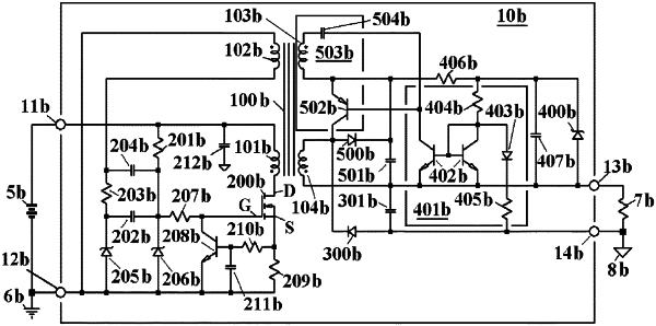
the circuitry comprises first circuitry and second circuitry, wherein, when the circuitry is connected to control the flyback converter, (i) the first circuitry is on the converter primary side and (ii) the second circuitry is on the converter secondary side;
the second circuitry (i) determines when to turn on the primary-side switch based on output port voltage or current at the output port and (ii) generates corresponding demand pulses;
the converter secondary side is configured to transmit the demand pulses to the converter primary side;
the first circuitry is configured to turn on the primary-side switch in response to the demand pulses conveyed from the converter secondary side to the converter primary side, wherein the first circuitry, and not the second circuitry, originates the determination of when to turn off the primary-side switch;
frequency with which the primary-side switch is turned on is the frequency of the demand pulses conveyed from the converter secondary side to the converter primary side to regulate the output port voltage or current;
the first circuitry is configured to determine when to turn off the switch independent of the duration of the demand pulses;
the second circuitry is configured to generate the demand pulses when a feedback signal based on the output port voltage or current is smaller in magnitude than a reference signal; and
the circuitry is configured to regulate the output port by driving the feedback signal to match the reference signal.
|